This site is from a past semester! The current version will be here when the new semester starts.

Week 7 [Fri, Feb 19th] - Topics

Detailed Table of Contents


Guidance for the item(s) below:

Previously, you learned a number of techniques for specifying requirements. There's one more left, which we'll cover this week.

[W7.1] Requirements: Use Cases

Video Q+

W7.1a

Requirements → Specifying Requirements → Use Cases → Introduction

Can explain use cases

Use case: A description of a set of sequences of actions, including variants, that a system performs to yield an observable result of value to an actor.[ 📖 : uml-user-guideThe Unified Modeling Language User Guide, 2e, G Booch, J Rumbaugh, and I Jacobson ]

Actor: An actor (in a use case) is a role played by a user. An actor can be a human or another system. Actors are not part of the system; they reside outside the system.

A use case describes an interaction between the user and the system for a specific functionality of the system.

Example 1: 'transfer money' use case for an online banking system

System: Online Banking System (OBS)
Use case: UC23 - Transfer Money
Actor: User
MSS:
  1. User chooses to transfer money.
  2. OBS requests for details of the transfer.
  3. User enters the requested details.
  4. OBS requests for confirmation.
  5. User confirms.
  6. OBS transfers the money and displays the new account balance.
  Use case ends.
Extensions:
  3a. OBS detects an error in the entered data.
      3a1. OBS requests for the correct data.
      3a2. User enters new data.
      Steps 3a1-3a2 are repeated until the data entered are correct.
      Use case resumes from step 4.
  
  3b. User requests to effect the transfer in a future date.
      3b1. OBS requests for confirmation.
      3b2. User confirms future transfer.
      Use case ends.
  
  *a. At any time, User chooses to cancel the transfer.
      *a1. OBS requests to confirm the cancellation.
      *a2. User confirms the cancellation.
      Use case ends.

Example 2: 'upload file' use case of an LMS


UML includes a diagram type called use case diagrams that can illustrate use cases of a system visually, providing a visual ‘table of contents’ of the use cases of a system.

In the example on the right, note how use cases are shown as ovals and user roles relevant to each use case are shown as stick figures connected to the corresponding ovals.

Use cases capture the functional requirements of a system.


W7.1b

Requirements → Specifying Requirements → Use Cases → Identifying

Can use use cases to list functional requirements of a simple system

A use case is an interaction between a system and its actors.

Actors in Use Cases

Actor: An actor (in a use case) is a role played by a user. An actor can be a human or another system. Actors are not part of the system; they reside outside the system.

Some example actors for a Learning Management System:

  • Actors: Guest, Student, Staff, Admin, an exam management systemExamSys, a library management systemLibSys.

A use case can involve multiple actors.

  • Software System: LearnSys
  • Use case: UC01 Conduct Survey
  • Actors: Staff, Student

An actor can be involved in many use cases.

  • Software System: LearnSys
  • Actor: Staff
  • Use cases: UC01 Conduct Survey, UC02 Set Up Course Schedule, UC03 Email Class, ...

A single person/system can play many roles.

  • Software System: LearnSys
  • Person: a student
  • Actors (or Roles): Student, Guest, Tutor

Many persons/systems can play a single role.

  • Software System: LearnSys
  • Actor (or role): Student
  • Persons that can play this role: undergraduate student, graduate student, a staff member doing a part-time course, exchange student

Use cases can be specified at various levels of detail.

Consider the three use cases given below. Clearly, (a) is at a higher level than (b) and (b) is at a higher level than (c).

  • System: LearnSys
  • Use cases:
    a. Conduct a survey
    b. Take the survey
    c. Answer survey question

While modeling user-system interactions,

  • Start with high level use cases and progressively work toward lower level use cases.
  • Be mindful of which level of detail you are working at and not to mix use cases of different levels.

Exercises


W7.1c

Requirements → Specifying Requirements → Use Cases → Details

Requirements → Specifying Requirements → Use Cases → Introduction


Can specify details of a use case in a structured format

Writing use case steps

The main body of the use case is a sequence of steps that describes the interaction between the system and the actors. Each step is given as a simple statement describing who does what.

An example of the main body of a use case.

  1. Student requests to upload file
  2. LMS requests for the file location
  3. Student specifies the file location
  4. LMS uploads the file

A use case describes only the externally visible behavior, not internal details, of a system i.e. should minimize details that are not part of the interaction between the user and the system.

This example use case step refers to behaviors not externally visible.

  1. LMS saves the file into the cache and indicates success.

A step gives the intention of the actor (not the mechanics). That means UI details are usually omitted. The idea is to leave as much flexibility to the UI designer as possible. That is, the use case specification should be as general as possible (less specific) about the UI.

The first example below is not a good use case step because it contains UI-specific details. The second one is better because it omits UI-specific details.

Bad : User right-clicks the text box and chooses ‘clear’

Good : User clears the input

A use case description can show loops too.

An example of how you can show a loop:

Software System: SquareGame
Use case: Each use case can be given a unique identification for easier cross reference. UC02 - Play a Game
Actors: Player (multiple players)

  1. A Player starts the game.
  2. SquareGame asks for player names.
  3. Each Player enters his own name.
  4. SquareGame shows the order of play.
  5. SquareGame prompts for the current Player to throw a die.
  6. Current Player adjusts the throw speed.
  7. Current Player triggers the die throw.
  8. SquareGame shows the face value of the die.
  9. SquareGame moves the Player's piece accordingly.
    Steps 5-9 are repeated for each Player, and for as many rounds as required until a Player reaches the 100th square.
  10. SquareGame shows the Winner.

Use case ends.

The Main Success Scenario (MSS) describes the most straightforward interaction for a given use case, which assumes that nothing goes wrong. This is also called the Basic Course of Action or the Main Flow of Events of a use case.

Note how the MSS in the example below assumes that all entered details are correct and ignores problems such as timeouts, network outages etc. For example, the MSS does not tell us what happens if the user enters incorrect data.

System: Online Banking System (OBS)
Use case: UC23 - Transfer Money
Actor: User
MSS:

  1. User chooses to transfer money.
  2. OBS requests for details of the transfer.
  3. User enters the requested details.
  4. OBS requests for confirmation.
  5. OBS transfers the money and displays the new account balance.

Use case ends.

Extensions are "add-on"s to the MSS that describe exceptional/alternative flow of events. They describe variations of the scenario that can happen if certain things are not as expected by the MSS. Extensions appear below the MSS.

This example adds some extensions to the use case in the previous example.

System: Online Banking System (OBS)
Use case: UC23 - Transfer Money
Actor: User
MSS:
  1. User chooses to transfer money.
  2. OBS requests for details of the transfer.
  3. User enters the requested details.
  4. OBS requests for confirmation.
  5. User confirms.
  6. OBS transfers the money and displays the new account balance.
  Use case ends.
Extensions:
  3a. OBS detects an error in the entered data.
      3a1. OBS requests for the correct data.
      3a2. User enters new data.
      Steps 3a1-3a2 are repeated until the data entered are correct.
      Use case resumes from step 4.
  
  3b. User requests to effect the transfer in a future date.
      3b1. OBS requests for confirmation.
      3b2. User confirms future transfer.
      Use case ends.
  
  *a. At any time, User chooses to cancel the transfer.
      *a1. OBS requests to confirm the cancellation.
      *a2. User confirms the cancellation.
      Use case ends.

  *b. At any time, 120 seconds lapse without any input from the User.
      *b1. OBS cancels the transfer.
      *b2. OBS informs the User of the cancellation.
      Use case ends.

Note that the numbering style is not a universal rule but a widely used convention. Based on that convention,

  • either of the extensions marked 3a. and 3b. can happen just after step 3 of the MSS.
  • the extension marked as *a. can happen at any step (hence, the *).

When separating extensions from the MSS, keep in mind that the MSS should be self-contained. That is, the MSS should give us a complete usage scenario.

Also note that it is not useful to mention events such as power failures or system crashes as extensions because the system cannot function beyond such catastrophic failures.

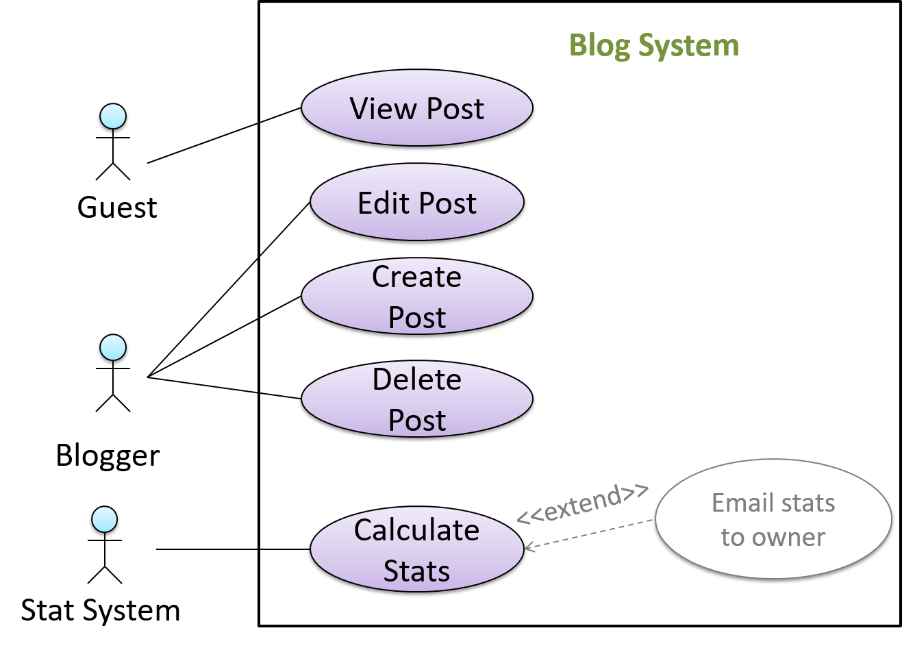
In use case diagrams you can use the <<extend>> arrows to show extensions. Note the direction of the arrow is from the extension to the use case it extends and the arrow uses a dashed line.

A use case can include another use case. Underlined text is commonly used to show an inclusion of a use case.

This use case includes two other use cases, one in step 1 and one in step 2.

  • Software System: LearnSys
  • Use case: UC01 - Conduct Survey
  • Actors: Staff, Student
  • MSS:
    1. Staff creates the survey (UC44).
    2. Student completes the survey (UC50).
    3. Staff views the survey results.
      Use case ends.

Inclusions are useful,

  • when you don't want to clutter a use case with too many low-level steps.
  • when a set of steps is repeated in multiple use cases.

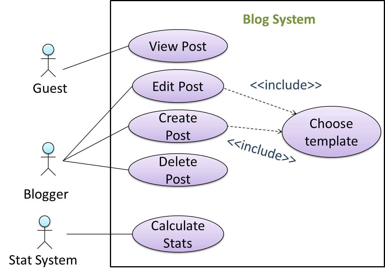
You use a dotted arrow and an <<include>> annotation to show use case inclusions in a use case diagram. Note how the arrow direction is different from the <<extend>> arrows.

Preconditions specify the specific state you expect the system to be in before the use case starts.

Software System: Online Banking System
Use case: UC23 - Transfer Money
Actor: User
Preconditions: User is logged in
MSS:

  1. User chooses to transfer money.
  2. OBS requests for details for the transfer.
    ...

Guarantees specify what the use case promises to give us at the end of its operation.

Software System: Online Banking System
Use case: UC23 - Transfer Money
Actor: User
Preconditions: User is logged in.
Guarantees:

  • Money will be deducted from the source account only if the transfer to the destination account is successful.
  • The transfer will not result in the account balance going below the minimum balance required.

MSS:

  1. User chooses to transfer money.
  2. OBS requests for details for the transfer.
    ...

Exercises


W7.1d

Requirements → Specifying Requirements → Use Cases → Usage

Can optimize the use of use cases

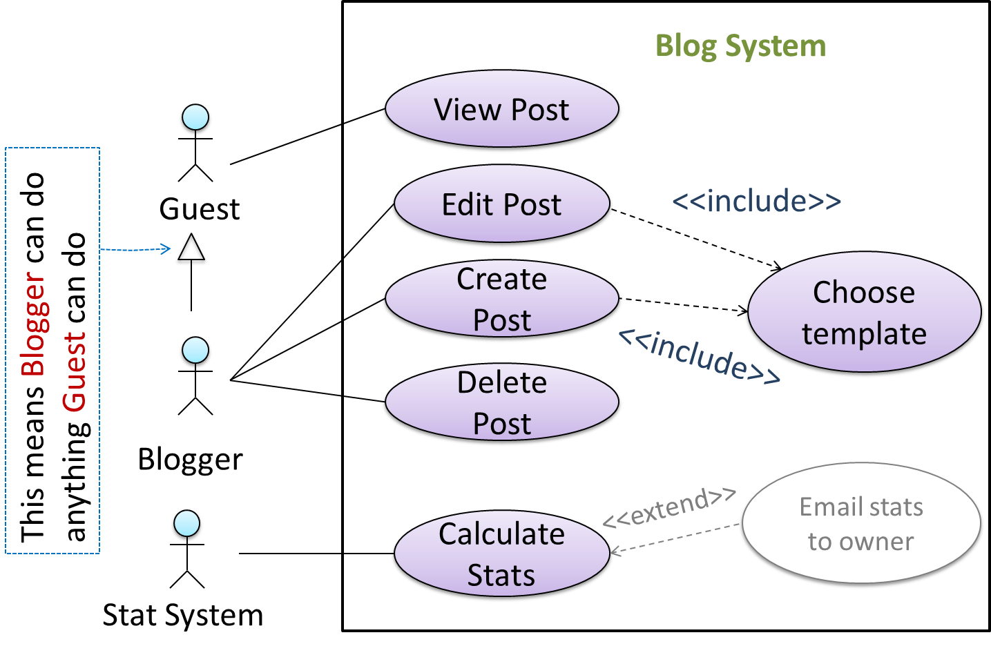
You can use actor generalization in use case diagrams using a symbol similar to that of UML notation for inheritance.

In this example, actor Blogger can do all the use cases the actor Guest can do, as a result of the actor generalization relationship given in the diagram.

Do not over-complicate use case diagrams by trying to include everything possible. A use case diagram is a brief summary of the use cases that is used as a starting point. Details of the use cases can be given in the use case descriptions.

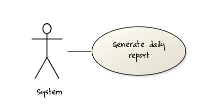
Some include ‘System’ as an actor to indicate that something is done by the system itself without being initiated by a user or an external system.

The diagram below can be used to indicate that the system generates daily reports at midnight.

However, others argue that only use cases providing value to an external user/system should be shown in the use case diagram. For example, they argue that view daily report should be the use case and generate daily report is not to be shown in the use case diagram because it is simply something the system has to do to support the view daily report use case.

You are recommended to follow the latter view (i.e. not to use System as a user). Limit use cases for modeling behaviors that involve an external actor.

UML is not very specific about the text contents of a use case. Hence, there are many styles for writing use cases. For example, the steps can be written as a continuous paragraph.

Use cases should be easy to read. Note that there is no strict rule about writing all details of all steps or a need to use all the elements of a use case.

There are some advantages of documenting system requirements as use cases:

  • Because they use a simple notation and plain English descriptions, they are easy for users to understand and give feedback.
  • They decouple user intention from mechanism (note that use cases should not include UI-specific details), allowing the system designers more freedom to optimize how a functionality is provided to a user.
  • Identifying all possible extensions encourages us to consider all situations that a software product might face during its operation.
  • Separating typical scenarios from special cases encourages us to optimize the typical scenarios.

One of the main disadvantages of use cases is that they are not good for capturing requirements that do not involve a user interacting with the system. Hence, they should not be used as the sole means to specify requirements.

Exercises


Follow up notes for the item(s) above:

Now that you know all the different ways of specifying requirements, **here is an example that shows how all techniques of specifying requirements can work together**:
Video Example: TeamFormer

Guidance for the item(s) below:

In the tP, you start with a code base that already has a certain design. What if there is no such design for you to start with? The next few topics look at how one can come up with such a design yourself.

[W7.2] Design: High-Level View

Video


Introduction

W7.2a

Design → Introduction → What

Can explain what is software design

Design is the creative process of transforming the problem into a solution; the solution is also called design. -- 📖 Software Engineering Theory and Practice, Shari Lawrence; Atlee, Joanne M. Pfleeger

Software design has two main aspects:

  • Product/external design: designing the external behavior of the product to meet the users' requirements. This is usually done by product designers with input from business analysts, user experience experts, user representatives, etc.
  • Implementation/internal design: designing how the product will be implemented to meet the required external behavior. This is usually done by software architects and software engineers.

Follow up notes for the item(s) above:

Now that you know there are two kinds of 'design', also note that this module focuses more on the internal design rather than the external design.

Design Approaches

W7.2b

Design → Design Approaches → Top-down and bottom-up design

Design → Design Approaches → Multi-Level Design → What


Can explain top-down and bottom-up design

Multi-level design can be done in a top-down manner, bottom-up manner, or as a mix.

  • Top-down: Design the high-level design first and flesh out the lower levels later. This is especially useful when designing big and novel systems where the high-level design needs to be stable before lower levels can be designed.
  • Bottom-up: Design lower level components first and put them together to create the higher-level systems later. This is not usually scalable for bigger systems. One instance where this approach might work is when designing a variation of an existing system or re-purposing existing components to build a new system.
  • Mix: Design the top levels using the top-down approach but switch to a bottom-up approach when designing the bottom levels.

Exercises


W7.2c

Design Approaches → Agile Design → Agile design

Can explain agile design

Agile design can be contrasted with full upfront design in the following way:

Agile designs are emergent, they’re not defined up front. Your overall system design will emerge over time, evolving to fulfill new requirements and take advantage of new technologies as appropriate. Although you will often do some initial architectural modeling at the very beginning of a project, this will be just enough to get your team going. This approach does not produce a fully documented set of models in place before you may begin coding. -- adapted from agilemodeling.com

Exercises


Guidance for the item(s) below:

As you do projects, you'll have to make design decisions e.g., decide between multiple design alternatives. Let us learn three fundamental design concepts that you can use in those decisions.

It is extremely important for you to know these three because they are like the DNA of every higher-level design concept.

[W7.3] Design: Fundamentals

Video Q+


Abstraction

W7.3a

Design → Design Fundamentals → Abstraction → What

Can explain abstraction

Abstraction is a technique for dealing with complexity. It works by establishing a level of complexity we are interested in, and suppressing the more complex details below that level.

The guiding principle of abstraction is that only details that are relevant to the current perspective or the task at hand need to be considered. As most programs are written to solve complex problems involving large amounts of intricate details, it is impossible to deal with all these details at the same time. That is where abstraction can help.

Data abstraction: abstracting away the lower level data items and thinking in terms of bigger entities

Within a certain software component, you might deal with a user data type, while ignoring the details contained in the user data item such as name, and date of birth. These details have been ‘abstracted away’ as they do not affect the task of that software component.

Control abstraction: abstracting away details of the actual control flow to focus on tasks at a higher level

print(“Hello”) is an abstraction of the actual output mechanism within the computer.

Abstraction can be applied repeatedly to obtain progressively higher levels of abstraction.

An example of different levels of data abstraction: a File is a data item that is at a higher level than an array and an array is at a higher level than a bit.

An example of different levels of control abstraction: execute(Game) is at a higher level than print(Char) which is at a higher level than an Assembly language instruction MOV.

Abstraction is a general concept that is not limited to just data or control abstractions.

Some more general examples of abstraction:

  • An OOP class is an abstraction over related data and behaviors.
  • An architecture is a higher-level abstraction of the design of a software.
  • Models (e.g., UML models) are abstractions of some aspect of reality.


Coupling

W7.3b

Design → Design Fundamentals → Coupling → What

Can explain coupling

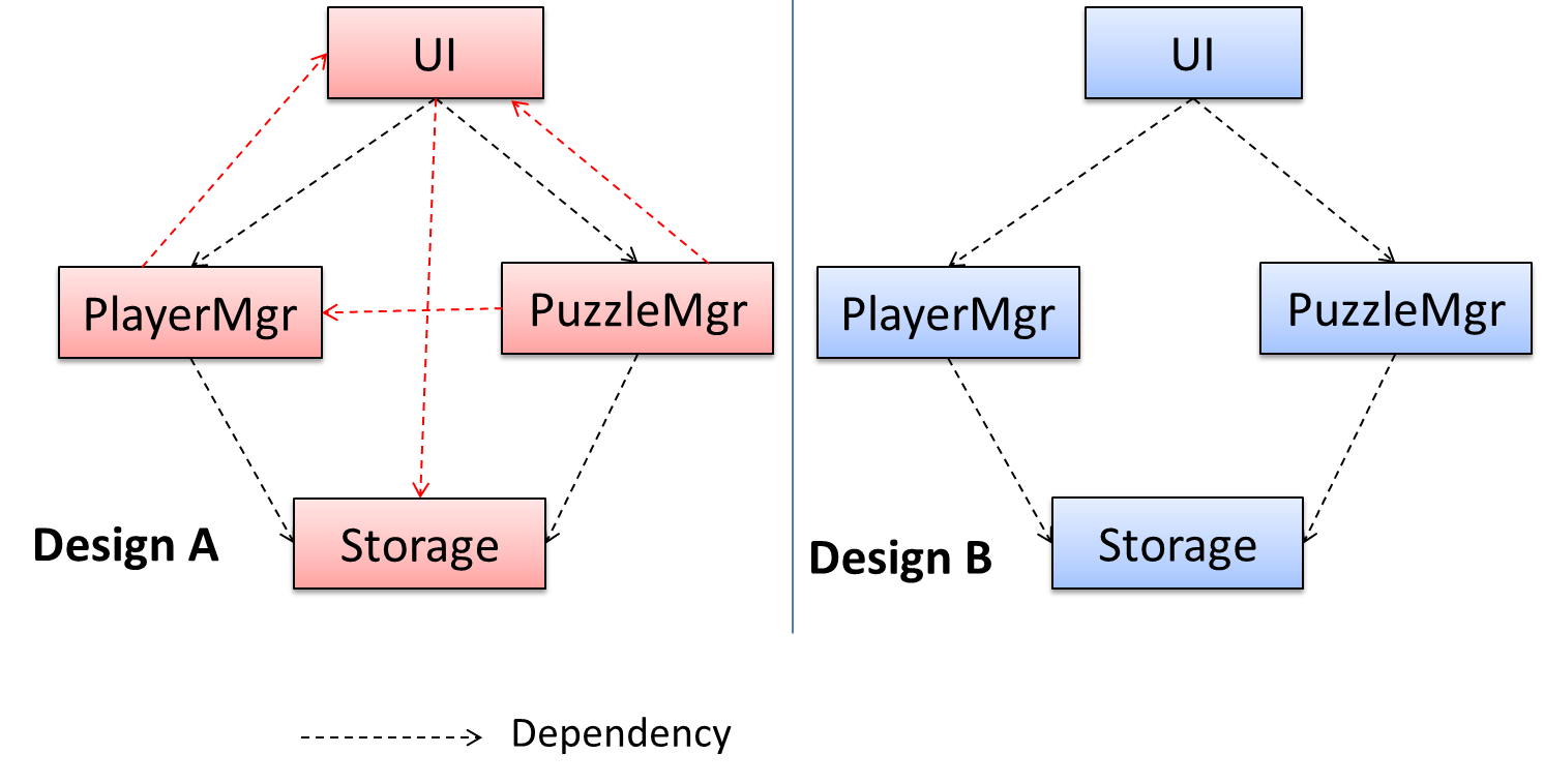
Coupling is a measure of the degree of dependence between components, classes, methods, etc. Low coupling indicates that a component is less dependent on other components. High coupling (aka tight coupling or strong coupling) is discouraged due to the following disadvantages:

  • Maintenance is harder because a change in one module could cause changes in other modules coupled to it (i.e. a ripple effect).
  • Integration is harder because multiple components coupled with each other have to be integrated at the same time.
  • Testing and reuse of the module is harder due to its dependence on other modules.

In the example below, design A appears to have more coupling between the components than design B.

Exercises


W7.3c

Design → Design Fundamentals → Coupling → How

Design → Design Fundamentals → Coupling → What


Can reduce coupling

X is coupled to Y if a change to Y can potentially require a change in X.

If the Foo class calls the method Bar#read(), Foo is coupled to Bar because a change to Bar can potentially (but not always) require a change in the Foo class e.g. if the signature of Bar#read() is changed, Foo needs to change as well, but a change to the Bar#write() method may not require a change in the Foo class because Foo does not call Bar#write().

code for the above example


Some examples of coupling: A is coupled to B if,

  • A has access to the internal structure of B (this results in a very high level of coupling)
  • A and B depend on the same global variable
  • A calls B
  • A receives an object of B as a parameter or a return value
  • A inherits from B
  • A and B are required to follow the same data format or communication protocol

Exercises


W7.3d : OPTIONAL

Design → Design Fundamentals → Coupling → Types of coupling


Cohesion

W7.3e

Design → Design Fundamentals → Cohesion → What

Can explain cohesion

Cohesion is a measure of how strongly-related and focused the various responsibilities of a component are. A highly-cohesive component keeps related functionalities together while keeping out all other unrelated things.

Higher cohesion is better. Disadvantages of low cohesion (aka weak cohesion):

  • Lowers the understandability of modules as it is difficult to express module functionalities at a higher level.
  • Lowers maintainability because a module can be modified due to unrelated causes (reason: the module contains code unrelated to each other) or many modules may need to be modified to achieve a small change in behavior (reason: because the code related to that change is not localized to a single module).
  • Lowers reusability of modules because they do not represent logical units of functionality.

W7.3f

Design → Design Fundamentals → Cohesion → How

Design → Design Fundamentals → Cohesion → What


Can increase cohesion

Cohesion can be present in many forms. Some examples:

  • Code related to a single concept is kept together, e.g. the Student component handles everything related to students.
  • Code that is invoked close together in time is kept together, e.g. all code related to initializing the system is kept together.
  • Code that manipulates the same data structure is kept together, e.g. the GameArchive component handles everything related to the storage and retrieval of game sessions.

Suppose a Payroll application contains a class that deals with writing data to the database. If the class includes some code to show an error dialog to the user if the database is unreachable, that class is not cohesive because it seems to be interacting with the user as well as the database.

Exercises


Guidance for the item(s) below:

In case you are the type who want to become a 'power user' of IDEs (it's not a bad idea, given the IDE is like the primary tool of a software engineer), given below are some more things you can do with IDEs.

[W7.4] IDEs: Advanced Features : OPTIONAL

W7.4a : OPTIONAL

Tools → IntelliJ IDEA → Productivity shortcuts


Guidance for the item(s) below:

As you start adding new code to the tP, let's also become aware of various approaches in integrating new code to a product.

[W7.5] Integration Approaches

Video

W7.5a

Implementation → Integration → Approaches → Late and one time versus early and frequent

Implementation → Integration → Introduction → What


Can explain how integration approaches vary based on timing and frequency

In terms of timing and frequency, there are two general approaches to integration: late and one-time, early and frequent.

Late and one-time: wait till all components are completed and integrate all finished components near the end of the project.

This approach is not recommended because integration often causes many component incompatibilities (due to previous miscommunications and misunderstandings) to surface which can lead to delivery delays i.e. Late integration → incompatibilities found → major rework required → cannot meet the delivery date.

Early and frequent: integrate early and evolve each part in parallel, in small steps, re-integrating frequently.

A it has all the high-level components needed for the first version in their minimal form, compiles, and runs but may not produce any useful output yetwalking skeleton can be written first. This can be done by one developer, possibly the one in charge of integration. After that, all developers can flesh out the skeleton in parallel, adding one feature at a time. After each feature is done, simply integrate the new code into the main system.

Here is an animation that compares the two approaches:


W7.5b

Implementation → Integration → Approaches → Big-bang versus incremental integration

Can explain how integration approaches vary based on amount merged at a time

Big-bang integration: integrate all components at the same time.

Big-bang is not recommended because it will uncover too many problems at the same time which could make debugging and bug-fixing more complex than when problems are uncovered incrementally.

Incremental integration: integrate a few components at a time. This approach is better than big-bang integration because it surfaces integration problems in a more manageable way.

Here is an animation that compares the two approaches:

Exercises


W7.5c : OPTIONAL

Implementation → Integration → Approaches → Top-down versus bottom-up integration


Guidance for the item(s) below:

Coordinating a team project is not easy. Given below are some very basic tools and techniques that are often used in planning, scheduling, and tracking projects.

[W7.6] Project Mgt: Scheduling and Tracking

Video

W7.6a

Project Management → Project Planning → Milestones

Can explain milestones

A milestone is the end of a stage which indicates significant progress. You should take into account dependencies and priorities when deciding on the features to be delivered at a certain milestone.

Each intermediate product release is a milestone.

In some projects, it is not practical to have a very detailed plan for the whole project due to the uncertainty and unavailability of required information. In such cases, you can use a high-level plan for the whole project and a detailed plan for the next few milestones.

Milestones for the Minesweeper project, iteration 1

Day Milestones
Day 1 Architecture skeleton completed
Day 3 ‘new game’ feature implemented
Day 4 ‘new game’ feature tested

W7.6b

Project Management → Project Planning → Buffers

Can explain buffers

A buffer is time set aside to absorb any unforeseen delays. It is very important to include buffers in a software project schedule because effort/time estimations for software development are notoriously hard. However, do not inflate task estimates to create hidden buffers; have explicit buffers instead. Reason: With explicit buffers, it is easier to detect incorrect effort estimates which can serve as feedback to improve future effort estimates.


W7.6c

Project Management → Project Planning → Issue trackers

Can explain issue trackers

Keeping track of project tasks (who is doing what, which tasks are ongoing, which tasks are done etc.) is an essential part of project management. In small projects, it may be possible to keep track of tasks using simple tools such as online spreadsheets or general-purpose/light-weight task tracking tools such as Trello. Bigger projects need more sophisticated task tracking tools.

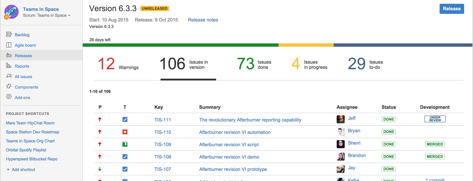
Issue trackers (sometimes called bug trackers) are commonly used to track task assignment and progress. Most online project management software such as GitHub, SourceForge, and BitBucket come with an integrated issue tracker.

A screenshot from the Jira Issue tracker software (Jira is part of the BitBucket project management tool suite):


W7.6d

Project Management → Project Planning → Work breakdown structure

Can explain work breakdown structures

A Work Breakdown Structure (WBS) depicts information about tasks and their details in terms of subtasks. When managing projects, it is useful to divide the total work into smaller, well-defined units. Relatively complex tasks can be further split into subtasks. In complex projects, a WBS can also include prerequisite tasks and effort estimates for each task.

The high level tasks for a single iteration of a small project could look like the following:

Task ID Task Estimated Effort Prerequisite Task
A Analysis 1 man day -
B Design 2 man day A
C Implementation 4.5 man day B
D Testing 1 man day C
E Planning for next version 1 man day D

The effort is traditionally measured in man hour/day/month i.e. work that can be done by one person in one hour/day/month. The Task ID is a label for easy reference to a task. Simple labeling is suitable for a small project, while a more informative labeling system can be adopted for bigger projects.

An example WBS for a game development project.

Task ID Task Estimated Effort Prerequisite Task
A High level design 1 man day -
B Detail design
  1. User Interface
  2. Game Logic
  3. Persistency Support
2 man day
  • 0.5 man day
  • 1 man day
  • 0.5 man day
A
C Implementation
  1. User Interface
  2. Game Logic
  3. Persistency Support
4.5 man day
  • 1.5 man day
  • 2 man day
  • 1 man day
  • B.1
  • B.2
  • B.3
D System Testing 1 man day C
E Planning for next version 1 man day D

All tasks should be well-defined. In particular, it should be clear as to when the task will be considered done.

Some examples of ill-defined tasks and their better-defined counterparts:

Bad Better
more coding implement component X
do research on UI testing find a suitable tool for testing the UI

Exercises


W7.6e

Project Management → Project Planning → Gantt charts

Can explain Gantt charts

A Gantt chart is a 2-D bar-chart, drawn as time vs tasks (represented by horizontal bars).

A sample Gantt chart:

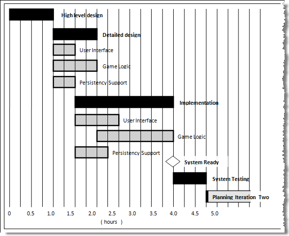
In a Gantt chart, a solid bar represents the main task, which is generally composed of a number of subtasks, shown as grey bars. The diamond shape indicates an important deadline/deliverable/milestone.


W7.6f : OPTIONAL

Project Management → Project Planning → PERT charts


W7.6g

Project Management → Teamwork → Team structures

Can explain common team structures

Given below are three commonly used team structures in software development. Irrespective of the team structure, it is a good practice to assign roles and responsibilities to different team members so that someone is clearly in charge of each aspect of the project. In comparison, the ‘everybody is responsible for everything’ approach can result in more chaos and hence slower progress.
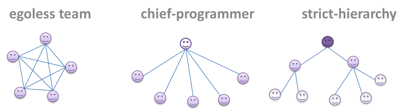
Egoless team

In this structure, every team member is equal in terms of responsibility and accountability. When any decision is required, consensus must be reached. This team structure is also known as a democratic team structure. This team structure usually finds a good solution to a relatively hard problem as all team members contribute ideas.

However, the democratic nature of the team structure bears a higher risk of falling apart due to the absence of an authority figure to manage the team and resolve conflicts.

Chief programmer team

Frederick Brooks proposed that software engineers learn from the medical surgical team in an operating room. In such a team, there is always a chief surgeon, assisted by experts in other areas. Similarly, in a chief programmer team structure, there is a single authoritative figure, the chief programmer. Major decisions, e.g. system architecture, are made solely by him/her and obeyed by all other team members. The chief programmer directs and coordinates the effort of other team members. When necessary, the chief will be assisted by domain specialists e.g. business specialists, database experts, network technology experts, etc. This allows individual group members to concentrate solely on the areas in which they have sound knowledge and expertise.

The success of such a team structure relies heavily on the chief programmer. Not only must he/she be a superb technical hand, he/she also needs good managerial skills. Under a suitably qualified leader, such a team structure is known to produce successful work.

Strict hierarchy team

At the opposite extreme of an egoless team, a strict hierarchy team has a strictly defined organization among the team members, reminiscent of the military or a bureaucratic government. Each team member only works on his/her assigned tasks and reports to a single “boss”.

In a large, resource-intensive, complex project, this could be a good team structure to reduce communication overhead.

Exercises


Guidance for the item(s) below:

Continuing on the same theme, given below are more practices used in managing projects, particularly related to the revision control aspect.

[W7.7] Project Mgt: Workflows

Video Q+

W7.7a

Project Management → Revision Control → Forking flow

Can explain forking workflow

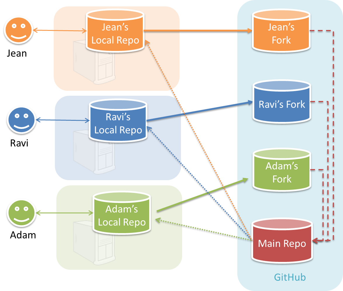
In the forking workflow, the 'official' version of the software is kept in a remote repo designated as the 'main repo'. All team members fork the main repo and create pull requests from their fork to the main repo.

To illustrate how the workflow goes, let’s assume Jean wants to fix a bug in the code. Here are the steps:

  1. Jean creates a separate branch in her local repo and fixes the bug in that branch.
    Common mistake: Doing the proposed changes in the master branch -- if Jean does that, she will not be able to have more than one PR open at any time because any changes to the master branch will be reflected in all open PRs.
  2. Jean pushes the branch to her fork.
  3. Jean creates a pull request from that branch in her fork to the main repo.
  4. Other members review Jean’s pull request.
  5. If reviewers suggested any changes, Jean updates the PR accordingly.
  6. When reviewers are satisfied with the PR, one of the members (usually the team lead or a designated 'maintainer' of the main repo) merges the PR, which brings Jean’s code to the main repo.
  7. Other members, realizing there is new code in the upstream repo, sync their forks with the new upstream repo (i.e. the main repo). This is done by pulling the new code to their own local repo and pushing the updated code to their own fork.
    Possible mistake: Creating another 'reverse' PR from the team repo to the team member's fork to sync the member's fork with the merged code. PRs are meant to go from downstream repos to upstream repos, not in the other direction.

One main benefit of this workflow is that it does not require most contributors to have write permissions to the main repository. Only those who are merging PRs need write permissions. The main drawback of this workflow is the extra overhead of sending everything through forks.


W7.7b

Tools → Git and GitHub → Forking workflow

Revision Control → Forking Workflow


Can follow Forking Workflow

You can follow the steps in the simulation of a forking workflow given below to learn how to follow such a workflow.

This activity is best done as a team.

Step 1. One member: set up the team org and the team repo.

  1. Create a GitHub organization for your team. The org name is up to you. We'll refer to this organization as team org from now on.

  2. Add a team called developers to your team org.

  3. Add team members to the developers team.

  4. Fork se-edu/samplerepo-workflow-practice to your team org. We'll refer to this as the team repo.

  5. Add the forked repo to the developers team. Give write access.

Step 2. Each team member: create PRs via own fork.

  1. Fork that repo from your team org to your own GitHub account.

  2. Create a branch named add-{your name}-info (e.g. add-johnTan-info) in the local repo.

  3. Add a file yourName.md into the members directory (e.g., members/jonhTan.md) containing some info about you into that branch.

  4. Push that branch to your fork.

  5. Create a PR from that branch to the master branch of the team repo.

Step 3. For each PR: review, update, and merge.

  1. [A team member (not the PR author)] Review the PR by adding comments (can be just dummy comments).

  2. [PR author] Update the PR by pushing more commits to it, to simulate updating the PR based on review comments.

  3. [Another team member] Approve and merge the PR using the GitHub interface.

  4. [All members] Sync your local repo (and your fork) with upstream repo. In this case, your upstream repo is the repo in your team org.

Step 4. Create conflicting PRs.

  1. [One member]: Update README: In the master branch, remove John Doe and Jane Doe from the README.md, commit, and push to the main repo.

  2. [Each team member] Create a PR to add yourself under the Team Members section in the README.md. Use a new branch for the PR e.g., add-johnTan-name.

Step 5. Merge conflicting PRs one at a time. Before merging a PR, you’ll have to resolve conflicts.

  1. [Optional] A member can inform the PR author (by posting a comment) that there is a conflict in the PR.

  2. [PR author] Resolve the conflict locally:

    1. Pull the master branch from the repo in your team org.
    2. Merge the pulled master branch to your PR branch.
    3. Resolve the merge conflict that crops up during the merge.
    4. Push the updated PR branch to your fork.
  3. [Another member or the PR author]: Merge the de-conflicted PR: When GitHub does not indicate a conflict anymore, you can go ahead and merge the PR.


W7.7c

Project Management → Revision Control → DRCS vs CRCS

Can explain DRCS vs CRCS

RCS can be done in two ways: the centralized way and the distributed way.

Centralized RCS (CRCS for short) uses a central remote repo that is shared by the team. Team members download (‘pull’) and upload (‘push’) changes between their own local repositories and the central repository. Older RCS tools such as CVS and SVN support only this model. Note that these older RCS do not support the notion of a local repo either. Instead, they force users to do all the versioning with the remote repo.

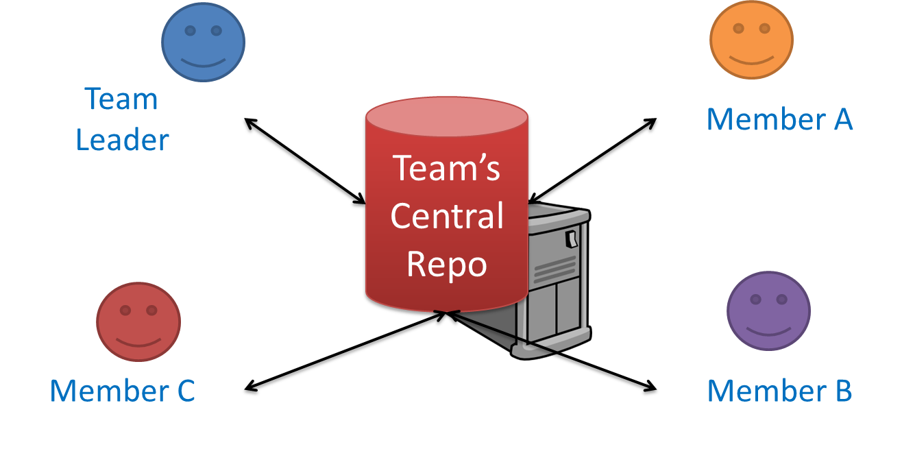
The centralized RCS approach without any local repos (e.g., CVS, SVN)

Distributed RCS (DRCS for short, also known as Decentralized RCS) allows multiple remote repos and pulling and pushing can be done among them in arbitrary ways. The workflow can vary differently from team to team. For example, every team member can have his/her own remote repository in addition to their own local repository, as shown in the diagram below. Git and Mercurial are some prominent RCS tools that support the distributed approach.

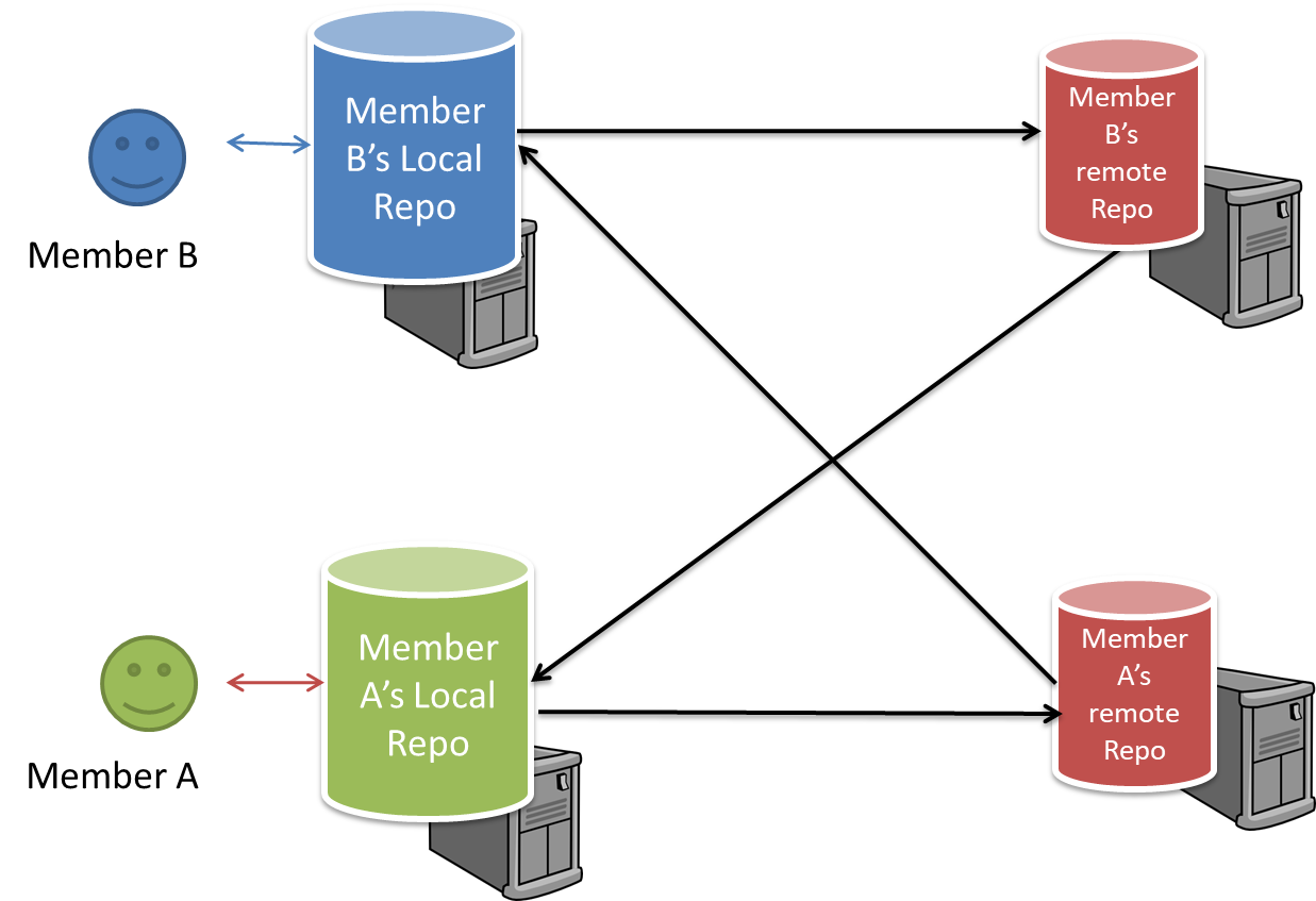
The decentralized RCS approach


W7.7d : OPTIONAL

Project Management → Revision Control → Feature branch flow


W7.7e : OPTIONAL

Project Management → Revision Control → Centralized flow